Last updated: April 13, 2024
|
Description
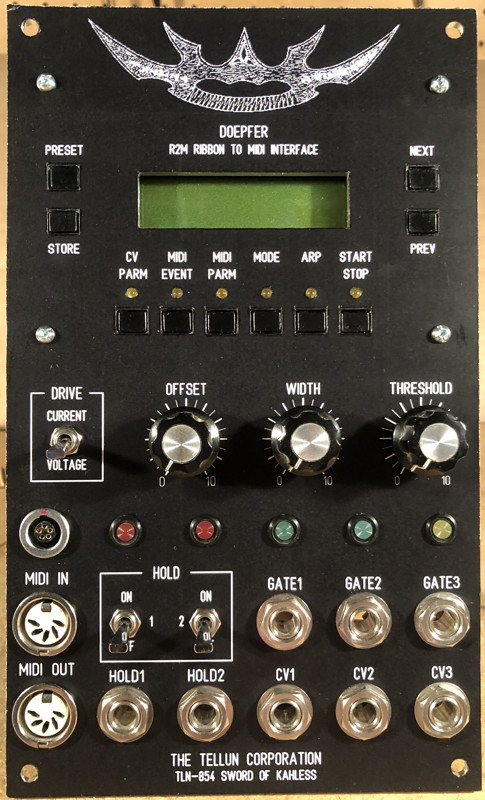
The TLN-854 Sword of Kahless is an amalgamation of a Doepfer R2M Ribbon to MIDI Interface and an unreleased ribbon controller I built for myself in early 2005. The R2M has some nice features (programmable, pitch quantization, no droop, MIDI in/out, position and pressure sensor) but is rather weak in the analogue control voltage section with only two outputs (position and pressure) and one gate output (position only). The TLN-854 remedies these limitations by using the R2M as the core of the ribbon controller and adding a substantially enhanced analogue output section (see feature list below). The R2M is itself not modified, merely enhanced, and thus all of its features are still available. You can download the R2M User Guide from Doepfer, but be warned that the section describing the analogue control voltage section is not correct; they need to update it.
In order to build this module, you will need: an R2M from Doepfer (including both the control box and the manual), the TLN-854 printed circuit board (and all necessary parts, see the User Guide for details), and a suitable panel. The R2M is mounted behind the top part of the panel using threaded standoffs epoxied to the back of the panel. The TLN-854 PCB is mounted behind the panel using Stooge brackets. You may also want to consider repackaging the R2M manual into a proper Bat'leth worthy of the warrior within you. Do a search for Bat'leth or Klingon weapons and you'll find plenty of fine examples.
Total current draw for TLN-854 and R2M is 81 mA @+15V, 30 mA @-15V, and 48 mA @+5V.
|
Features
- VOLTAGE or CURRENT DRIVE. The R2M uses a voltage source to drive the ribbon. This is bad because if you touch the ribbon in two places at once you get a voltage that is somewhere in between the two positions. A better solution is a current source which gives you low note priority (or high note priority depending on the orientation of the ribbon) like that found on your old analogue monosynths. The DRIVE switch allows selecting either voltage or current drive for the position sensor.
- CV 1, GATE 1 with LED. CV 1 is the position output from the R2M. GATE 1 is a reconditioned version of the gate signal from the R2M. This is not your wimpy Terran +5 volt gate, like what you get from the R2M. This is a razor sharp 11.3 volt gate with an LED and a jumper to select either positive output voltage or S-TRIG style gate.
- CV 2 with OFFSET and WIDTH, GATE 2 with LED. The R2M can only generate voltages between 0 and +5 volts, useless if you want to use the ribbon like a pitch bend wheel. The OFFSET control adds a negative offset to CV 1 and presents this at the CV 2 output so you can set a zero voltage point anywhere along the ribbon and get both positive and negative voltages from the position sensor. The WIDTH control sets the width of the dead-band range around the zero point, from approximately +/- 1 volt to 0 volts (completely off). This makes it much easier to use the ribbon as a pitch bender since you don't have to be so precise when you tap the middle (0 volt) position. GATE 2 is a new gate signal that is derived directly from the position sensor, not from GATE 1. The gate signal from the R2M is odd; there are some operating modes where no gate signal is generated at all, and some operating modes where the gate signal will retrigger as you slide your finger along the ribbon. GATE 2 is a gate signal that goes on when you touch the ribbon and stays on until you stop touching the ribbon. Like GATE 1, GATE 2 is a razor sharp 11.3 volt gate with an LED and a jumper to select either positive output voltage or S-TRIG style gate.
- HOLD 1 and HOLD 2. The position output from the R2M always holds the last voltage when you release your finger from the ribbon. What on earth were they thinking? It's like having the sustain pedal permanantly pressed on your keyboard. There needs to be a way to turn the hold function off so that the output voltage drops to 0 volts when you release your finger from the ribbon (think Keith Emerson playing Tarkus and shooting fireworks from his ribbon controller). To remedy this, CV 1 and CV2 both have HOLD ON/OFF switches, with LEDs to indicate when HOLD is enabled, and jacks for turning the hold function ON and OFF with an external control signal.
- CV 3, GATE 3 with LED and THRESHOLD. CV 3 is the pressure sensor output from the R2M. GATE 3 is a gate whose trigger point is set by the THRESHOLD control (gate goes high when pressure sensor output exceeds THRESHOLD). Like GATE 1, GATE 3 is a razor sharp 11.3 volt gate with an LED and a jumper to select either positive output voltage or S-TRIG style gate.
|
Availability: Sold Out
|
Downloads
The User Guide does not contain detailed explanations on how to install parts or which kinds of solder to use. The intended audience is the experienced kit builder who is quite comfortable building a circuit from a description, a parts list, and a schematic. Calibration routines are included.
View the TLN-854 User Guide rev 1.0 (pdf)
Graze over the TLN-854 Schematics rev 1.0 (pdf)
Detailed panel cutout diagram (pdf) with notes for those who want to build their own panel. The layout is slightly different than the final panel design seen in the FPD file below.
Front Panel Designer file of the final panel design (does not include the graphic at the top of the panel).
Photoshop file of the final panel design (which includes the graphic).
|
Pictures
 |
 |
 |
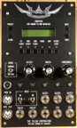
| Final Panel |
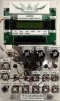
Prototype with
Clear Panel |
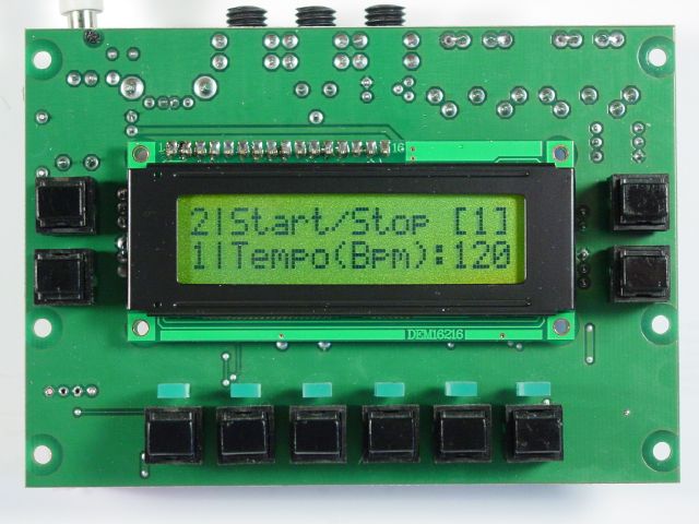
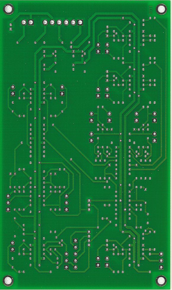
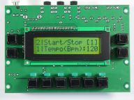
Front View of R2M PCB
4.65" (W) x 3.25" (H) |
 |
 |
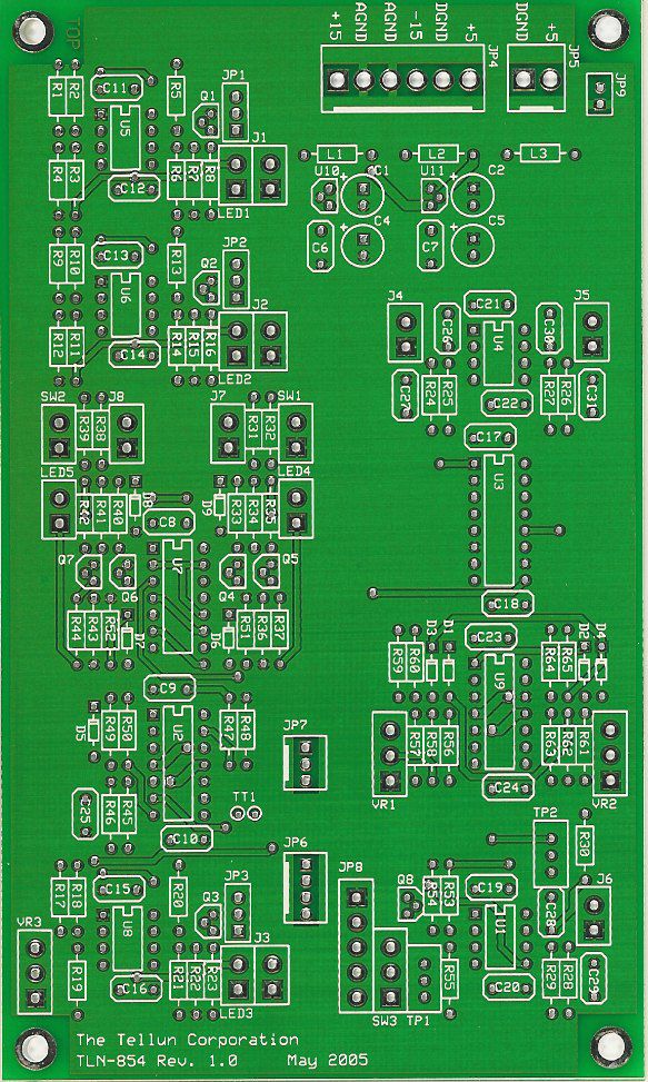
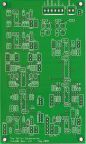
| PCB Top View |
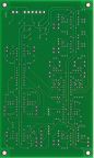
PCB Bottom View |
Construction photos.
|
|