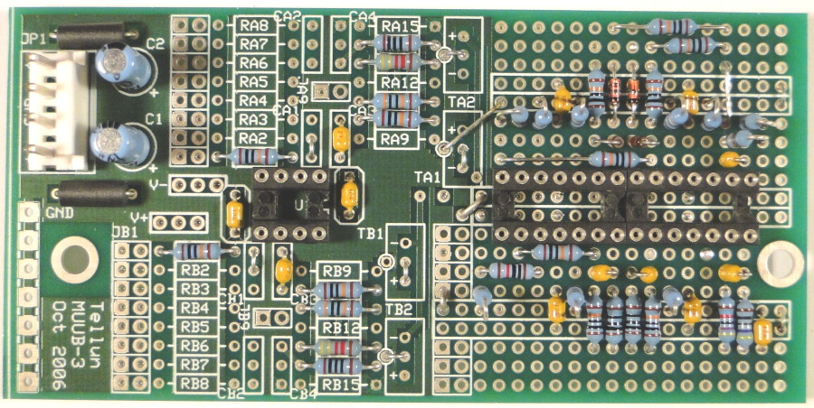
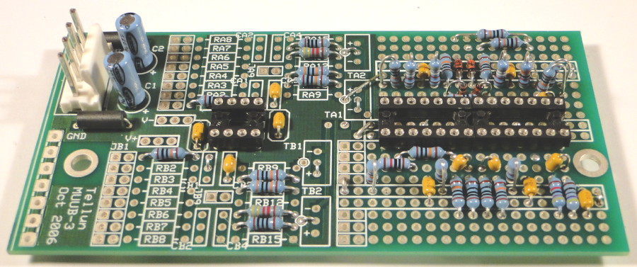
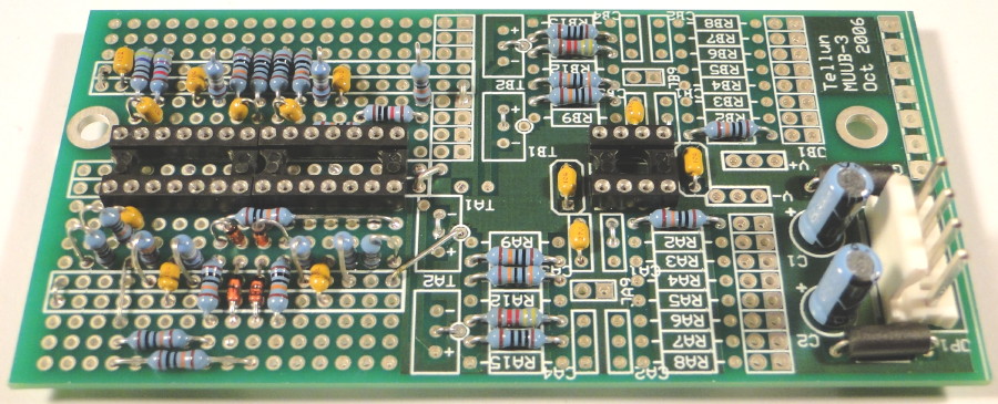
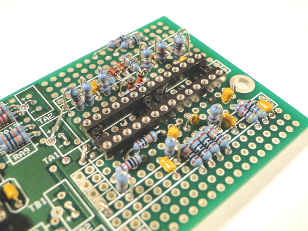
Everything on page 1 of the schematic can be built onto one MUUB-3 PCB. The A+5 and A-5 circuits are constructed on the left half of the PCB with a TL072 dual op-amp. Everything else from page 1 is constructed on the right half of the PCB in the GPA (general purpose area) using two TL074 quad op-amps. There are two busses running underneath the TL074s, one buss is for +15V, the other is for -15V. The other four busses in the GPA are connected to ground. You'll have to run jumpers from the left half of the PCB to the busses in the GPA. Most of the components can be placed on the topside of the board, but I put 3 resistors and 3 jumpers on the underside. Coax wires running to the front panel are best attached to JA9, JB9 (left side of PCB for A+5 and A-5) and the seven pads near TB1 and TB2 (middle of PCB for IN A, INV A, POS A, NEG A, and FWR A). The TL074 chips I used hung over the edges of the sockets a bit. I had to use a Dremel to trim the edges of them in order to get them to butt up next to each other when inserted into the sockets.
Everything on page 2 of the schematic can be built onto a second MUUB-3 board (for the B channel). The B channel circuit is identical to the A channel, so just build a duplicate of the A channel. You only need the ferrite beads and power connector on one of the MUUB-3 PCBs (I put them on the B channel PCB). I split the 22 uF power supply bypass caps up by putting 10 uF caps onto each of the MUUB-3 PCBs.
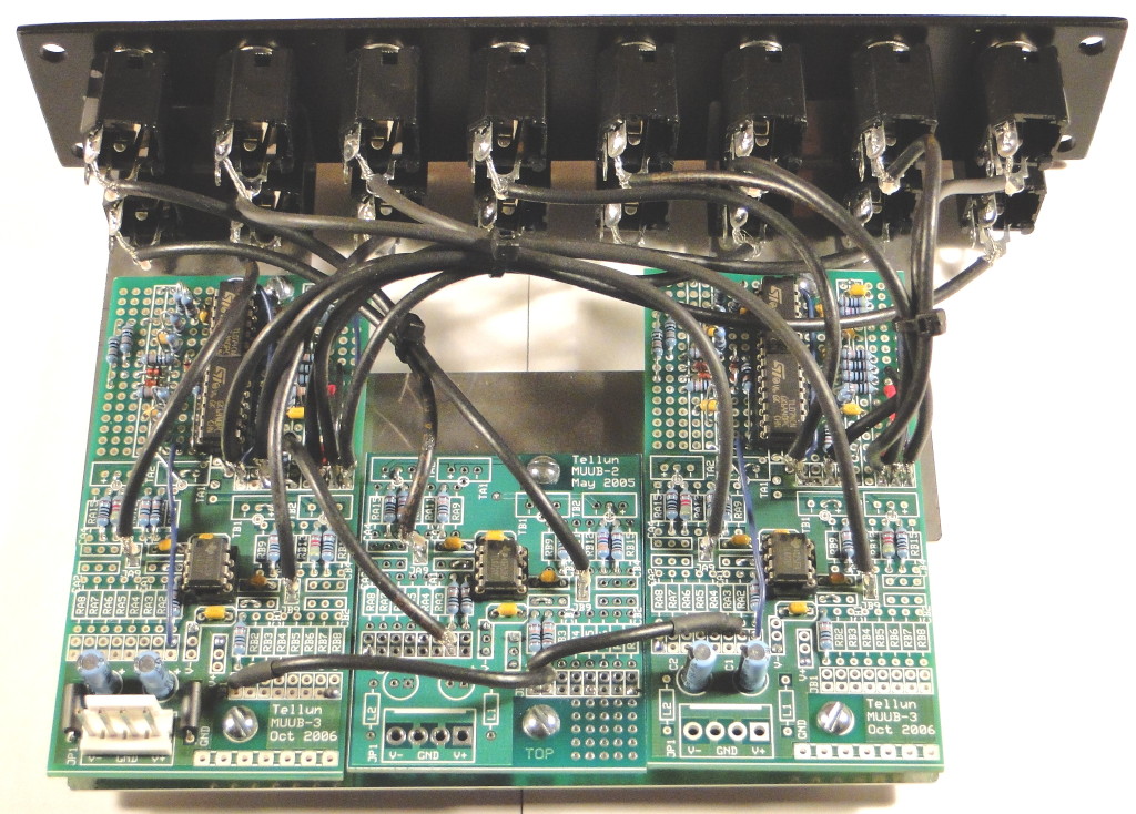
Everything on page 3 of the schematic (A+B and A-B) can be built onto a MUUB-2 board. Study the pictures below to see how I put it all together.
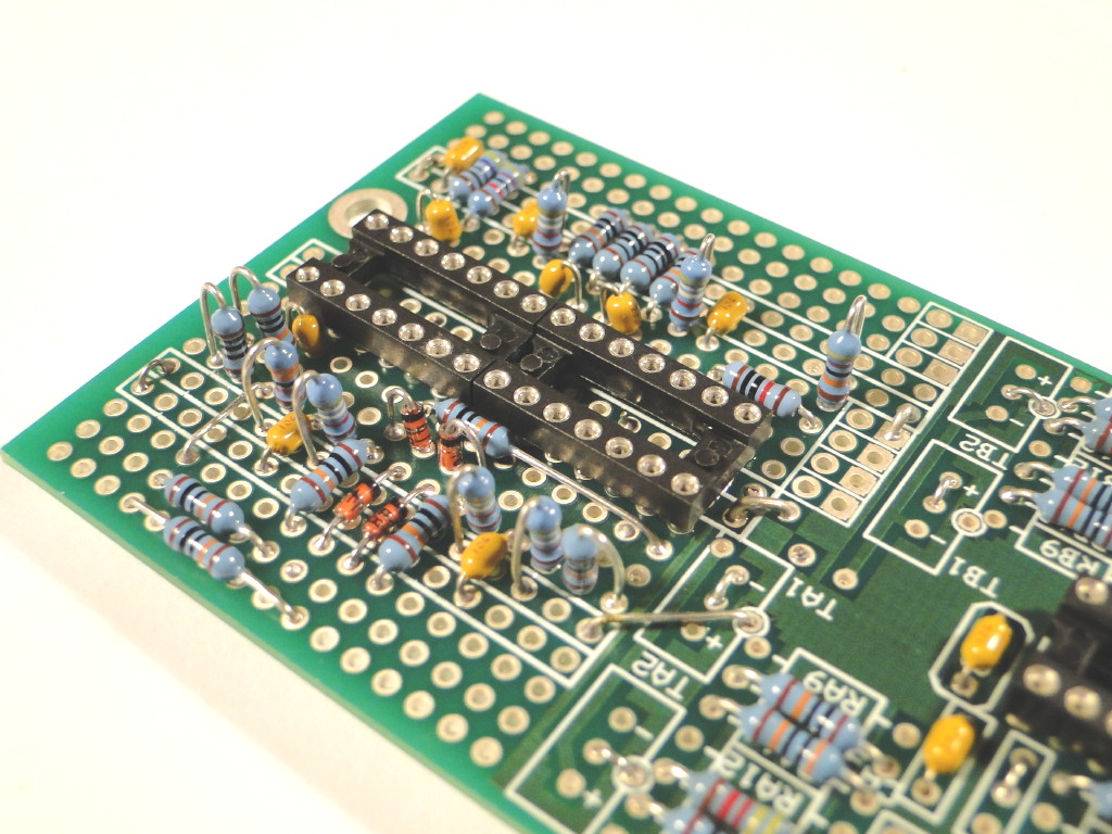
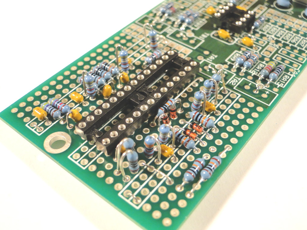
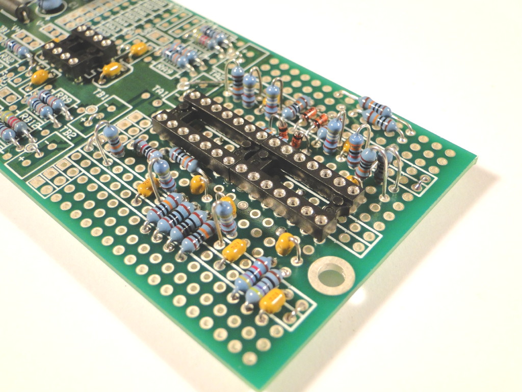
B Channel Topside Views. The A Channel is identical except it doesn't have the power connector and ferrite beads:
| |
|
|
|
| |
|
|
|
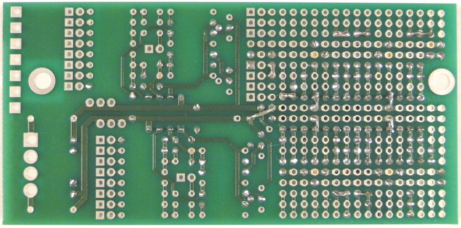
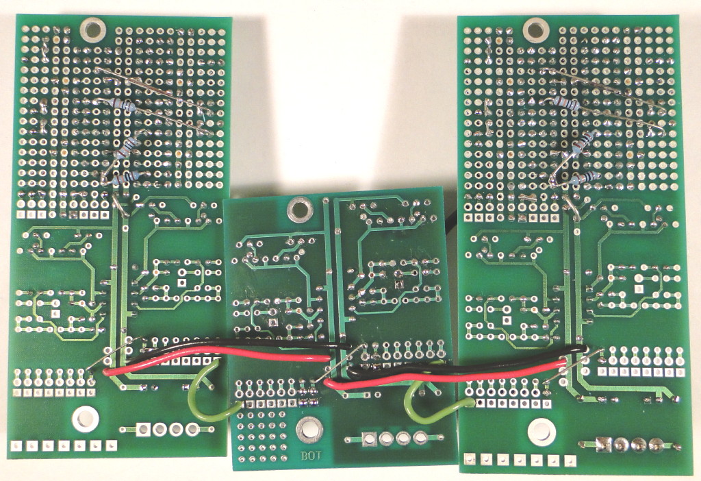
B Channel Underside Views. The A Channel is identical except it doesn't have the power connector and ferrite beads:
 |
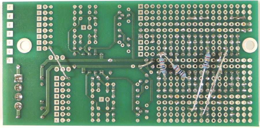 |
A+B and A-B circuits on MUUB-2:
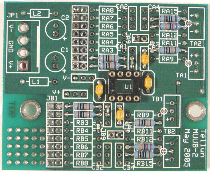 |
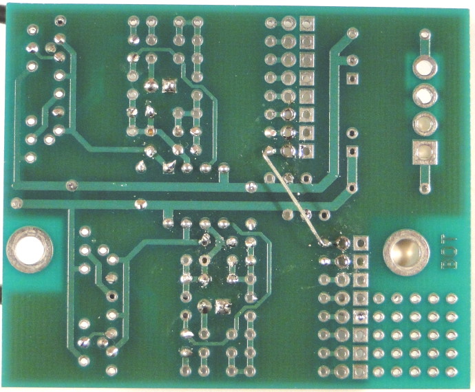 |
All three PCBs connected together, power supply connections between PCBs are on the underside:
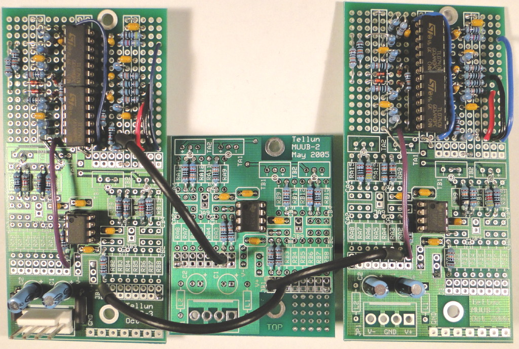 |
 |
 |