Back to All Mod Cons
Last updated: March 21, 2010
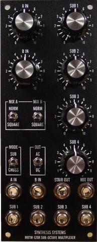
1. Increase Output LevelChanged R10 from 33K to 200K to get 10 Vpp output from any one of the sub octave outputs. As designed, the only way to achieve 10 Vpp output is to have the two IN level knobs and all of the SUB level knobs set to 10. With this mod, the two inputs and each of the sub octaves will output 10 Vpp when their associated output level knob is set to 10. Note that this mod multiplies each of the 5 Vpp outputs from the logic circuitry by two to get 10 Vpp levels. This doubling of amplitude also applies to the A IN and B IN signals. If the MIX A switch is set to NORM and a 10 Vpp signal is applied to the A input, the output level will be 20 Vpp when the A IN knob is set to 10. The same holds true for the B input. A voltage divider can be constructed directly across the input jack but I haven't bothered to do this; I can just turn down the A IN and B IN levels to compensate. I undid this mod after adding the DB-120 daughterboard; it is superfluous with the daughterboard. |
2. Add DB-120 DaughterboardInformation regarding the DB-120 daughterboard can be found here. |
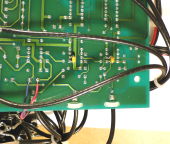
3. Add Deglitching Capacitors to ComparatorsI came across this tidbit regarding the MOTM-120 a few years ago: When it came to testing this module, I was a little perturbed that it didn't work as I expected. in sub mode, turning up each of the four sub octave pots produced glitches in the audio if I had signal on both the A IN and B IN jacks. This couldn't be right. ... This time I happened to put the scope probe on the non-inverting input of the input comparator, and lo, the glitching stopped. Aha.. the capacitance of the scope probe had stopped the clock jitter. Solution: I happened to have a couple of 18pF ceramic caps handy, so I put these across the non-inverting input and ground (Pins 2 & 1) of both of the 311 comparators. Problem solved. The module now appears to work as intended.... I made the same changes to my MOTM-120 modules (and so have a number of other people over the past few years) and I can confirm that this simple addition of two capacitors cures all kinds of ills with the MOTM-120 (and the modified MOTM-120R). The exact value of the capacitor isn't all that important, anything from 15 pF to 33 pF should work. The best place to add these two capacitors is on the underside of the PCB, directly between pins 2 and 1 of both comparators. Yes, it's a bit of work to remove the mounting bracket to reach the underside, but there isn't really any good place to add these capacitors on the topside. See the picture below for an example. |
