Last updated: January 24, 2003
|
1. Eliminate Unnecessary Components
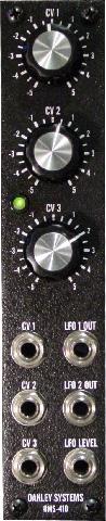
The following parts can all be left out if using the Stooge panel (shown left):
1. Mixer Section
- 3-way 0.1" header
- R23, R24, R25, R26, R35, R36, R37, R38
- C10, C11
- U3
2. Pad Switch
3. CV2 Driver For LFO2 VCA
4. Inverter
This clears up quite a bit of space on the PCB and allows adding the blinky light mod that follows below.
|
2. Add Blinky Light to LFO1 Output
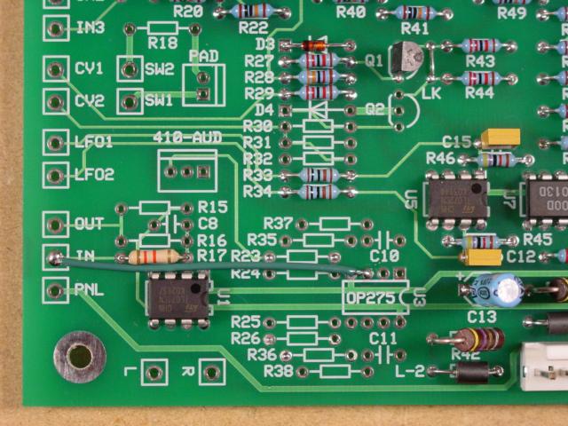
Added a bicolour Lumex LED to LFO1 output using the vacant area left after removing unnecessary components (see mod #1 above). The circuit is given below:
Procedure
- Must break trace to pin 3 of U1 so that the non-inverting input is not tied to ground. This trace is on the underside of the PCB.
- Add a 1.2K resistor (RX) between pin 3 of U1 and pin 1 of U5. I added this resistor to the underside of the board.
- Add a 1.2K resistor (RY) between pin 2 of U1 and ground. Put RY into the spot where R17 is supposed to go. This resistor sets the brightness of the LED, 1.2K worked the best for me. Set resistor RX (from step 2) to the same value as RY.
- Add a jumper wire from the IN connector to ground. I used pin 3 of U3 for the ground connection.
- Add a bicolour LED to the spot where C8 is supposed to go.
- Add U1 (TL071) as indicated on the PCB.
 |
 |
| PCB Top View |
The Twins |
Notes
- LED can be attached to LFO2 by using pin 7 of U5 (rather than pin 1 of U5). I chose LFO1 over LFO2 because LFO1 is used exclusively in SINGLE mode on the MOTM-410, and in the other two modes (DUAL, DUAL REV) my brain locks onto the faster LFO first.
- There is enough space around U1 to recreate the exact same circuit used to drive the LED on the MOTM-320. I tried both circuits and was happy with the simpler one presented here.
- There is enough space in the vacant area around U3 to create two of these LED driver circuits (to get LEDs for both LFO1 and LFO2). Don't need to use an OP275 for U3, a TL072 will work fine as an LED driver. I didn't do this because one LED was fine for my needs.
|
|