Back to Synth DIY Projects
Last updated: March 17, 2013
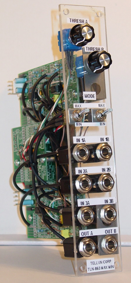
DescriptionThe TLN-863 Max Min Generator is a MUUB implementation of a Linear Or/And Gate from Jung's Op-Amp Cookbook. This circuit is very similar to Ken Stone's Analog Logic circuit and Dave Brown's Analogic circuit. With the MODE switch set to the MAX position, the output will be the maximum of inputs 1-3 (Linear Or). With the MODE switch set to the MIN position, the output will be the minimum of inputs 1-3 (Linear And). The THRESHOLD pot sets a voltage that is normalled to the input jacks when no signal is plugged into the jacks. This turns the circuit into a "Clipper" when the MODE switch is set to MIN (output voltage will not go below the THRESHOLD), and a "Clamper" when the MODE switch is set to MAX (output voltage will not exceed the THRESHOLD). The TLN-863 pictured at left features two independent channels (A & B) with the following controls:
Note that the panel layout for this module (and the rest of my MUUB utility modules) uses the smaller type of knob found on Encore Electronic's UEG and Frequency Shifter. Most people will probably hate this, but I wanted to get the most functionality in the least amount of space while still maintaining some semblance to the MOTM standard. To this end, all of my MUUB utility modules use a new layout grid that allows up to 6 pots with 4 jacks, or 4 pots with 8 jacks, on a 1U wide module. The TLN-863 Max Min Generator can be built using MUUB daughterboards. The first version I built (Rev 1) used two MUUB-4 boards and two MUUB-2 boards with the MUUB-2 boards stacked on top of each other. That version was a bit cumbersome to put together. I then realized I could simplify things considerably by using two MUUB-3 boards (Rev 2). Also, (for Rev 2) I noticed that there was no need to use small knobs since there is sufficient room for big knobs using the standard MOTM grid. Contact me if you wish to purchase PCBs. Total current draw for TLN-863 is 17 mA @+15V and 17 mA @-15V. |
||||||
DownloadsThe User Guide does not contain detailed explanations on how to install parts or which kinds of solder to use. The intended audience is the experienced kit builder who is quite comfortable building a circuit from a description, a parts list, and a schematic. Calibration routines are included. Note that the User Guide describes building a Max Min Generator using two MUUB-4 boards and two MUUB-2 boards (Rev 1). I don't recommend building it this way; you are better off building it using two MUUB-3 boards (Rev 2). See the Rev 2 construction photos and notes for more info. View the TLN-863 User Guide rev 1.1 (pdf) Graze over the TLN-863 Schematics rev 1.0 (pdf) Detailed panel cutout diagram (pdf) with notes for those who want to build their own panel (with the small knob layout). I copied an FPD file from Dave Brown and modified it for the TLN-863. I then printed out a screenshot of the FPD file using an inkjet printer and pasted it onto my plastic panel. It doesn't look too bad, especially in a dark room. |
||||||
Pictures
Rev 1 construction photos. I don't recommend building it this way. Rev 2 construction photos and notes. This is a more compact way to build a Max Min Generator. |
||||||
Sound SamplesThese samples demonstrate some uses of the TLN-863.
|