Back to Synth DIY Projects
Last updated: March 17, 2013
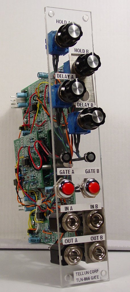
DescriptionThe TLN-866 Gate Processor is a gate delay, a pulse stretcher, and a gate generator. Any signal that momentarily exceeds +1.5V can be used to "arm" the processor and create a GATE signal at the output. This output GATE is held for the HOLD time but doesn't appear at the output until the DELAY time has passed. HOLD and DELAY times can be from 5 milliseconds to 10 seconds (or longer if you wish). A handy pushbutton on the front panel addresses the need for a manual GATE signal in your synth. A bicolour LED is used to indicate the processor's status: RED when the processor is armed and GREEN when the output goes high. The TLN-866 can be used to create an echo of a gate signal. For example, if the HOLD and DELAY times are 4 seconds, a one second long gate signal at the input will result in a one second long gate signal at the output 3 seconds after the input gate has gone low. Spooky. The dual TLN-866 pictured at left features two independent channels (A & B) with the following controls:
Note that the panel layout for this module (and the rest of my MUUB utility modules) uses the smaller type of knob found on Encore Electronic's UEG and Frequency Shifter. Most people will probably hate this, but I wanted to get the most functionality in the least amount of space while still maintaining some semblance to the MOTM standard. To this end, all of my MUUB utility modules use a new layout grid that allows up to 6 pots with 4 jacks, or 4 pots with 8 jacks, on a 1U wide module. The TLN-866 Gate Processor can be built using MUUB daughterboards. The first version I built (Rev 1) used two MUUB-4 boards and two MUUB-2 boards with the MUUB-2 boards stacked on top of each other. That version was a bit cumbersome to put together. I then realized I could simplify things considerably by using two MUUB-3 boards (Rev 2). Contact me if you wish to purchase PCBs. Total current draw for a two channel TLN-866 (as shown at left) is 82 mA @+15V and 47 mA @-15V. |
||||||
DownloadsThe User Guide does not contain detailed explanations on how to install parts or which kinds of solder to use. The intended audience is the experienced kit builder who is quite comfortable building a circuit from a description, a parts list, and a schematic. Calibration routines are included. View the TLN-866 User Guide rev 1.0 (pdf) Graze over the TLN-866 Schematics rev 1.0 (pdf) Detailed panel cutout diagram (pdf) with notes for those who want to build their own panel. MOTM-style front panels for this module can be ordered from The Bridechamber. I copied an FPD file from Dave Brown and modified it for the TLN-866. I then printed out a screenshot of the FPD file using an inkjet printer and pasted it onto my plastic panel. It doesn't look too bad, especially in a dark room. |
||||||
Pictures
Rev 1 construction photos. I don't recommend building it this way. Rev 2 construction photos and notes. This is a more compact way to build a Gate Processor. |
||||||
Sound SamplesThese samples demonstrate some uses of the TLN-866. All samples are recorded without any added effects.
|