|
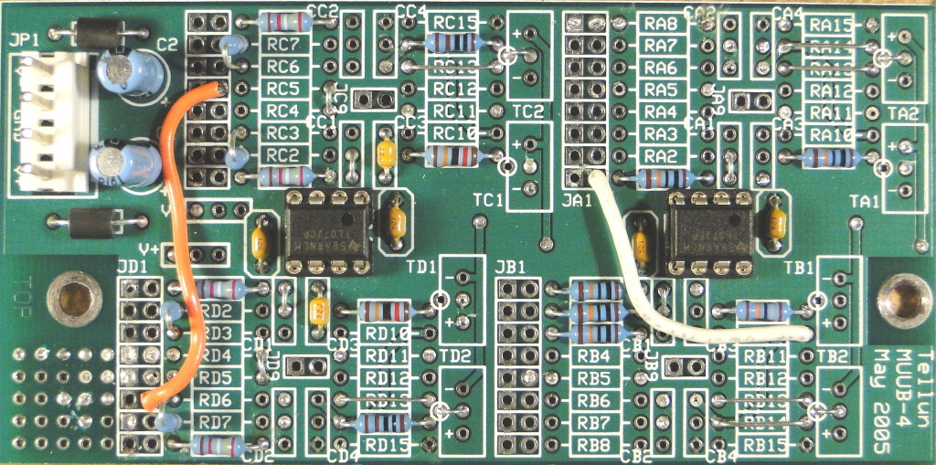
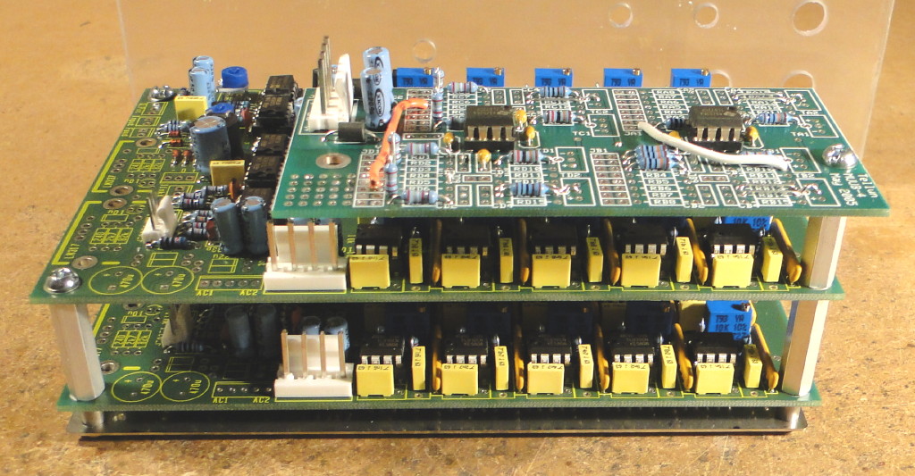
Below are details of my implementation of the JH String Filter into a 40 channel filter bank with input and output mixers. I used a MUUB-4 board to add the input and output mixers. The MUUB is attached to the stacked string filter PCBs using a 1" aluminum standoff. See the construction photos to see how the three PCBs are stacked together. Grab the schematic and follow along with the explanations below. 1. Level Control and Patch Point For All 40 ChannelsThe changes are quite simple for each channel, but due to there being 40 channels in total, the amount of extra wiring is quite substantial. Before beginning this modification, make sure you have lots of coax cable on hand and prepare to spend a lot of time planning how to route all the wires so you don't end up with a rat's nest. I probably spent just as many hours planning how to construct this module as actually building it. There are several choices for the 40 patch points. You can use standard TS phone jacks if you simply want an output for each of the 40 bandpass filters. If you use Switchcraft 114B jacks (or equivalent) you can create patch points for each of the 40 channels. This allows each channel to be an output-only, an input-only, or a SEND-RECEIVE patch point as found on many mixing boards. The latter requires INSERT cables that have a TRS plug on one end and two standard TS plugs for the SEND and RECEIVE signals (HOSA make these or you can make your own). However, if you wire the 114B jacks as described below you can still use standard TS phone plugs to get an output-only signal by inserting the plug halfway into the 114B jack so that the tip of the plug makes contact with the RING connection (not the TIP connection). Circuit DescriptionBelow is a sample of the original summing network (paraphrased from JH's schematics). There are four op-amps (U7A, U8A, U10A, U11A) that each create one of the four partials, only one of these is shown below (U11A). Each of these op-amps adds together the outputs from ten bandpass filters, only one of these is shown below (U140B). 
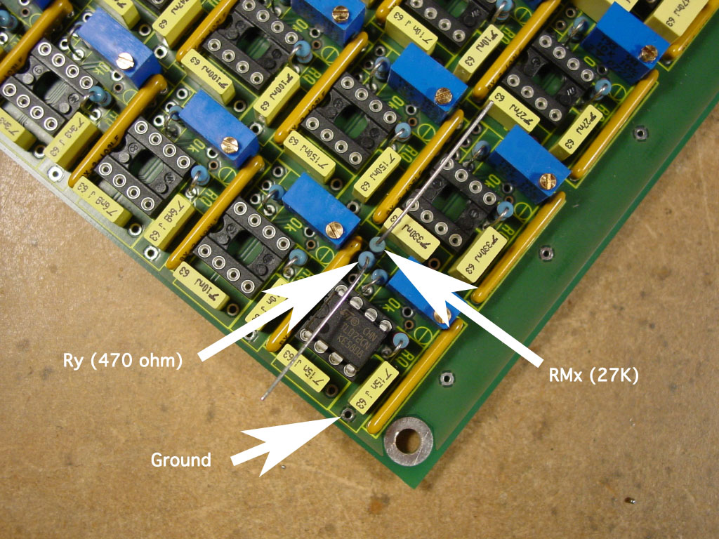
Below is a sample of the modified summing network. Resistor Ry (470 ohm) protects the op-amp from being accidentally shorted to ground when inserting cables into the 114B jack. The bandpass filter output goes to the RING and the TIP SWITCH on the 114B jack. With nothing plugged into the jack, the bandpass filter output is routed to the top of the 50K pot. The wiper of the pot sends a proportion of the bandpass filter output to the partial summing amp U11A via RMx40. 
Note that RMx40 and R58 were both changed from 10K to 27K. The reason for this is that, with a 50K linear pot, the original 10K resistors created a very lopsided loudness contour when the pot was rotated. I changed these to 27K because those values provided a fairly log-like response to my ears. You may choose to use a different value for RMx40 and R58, that's fine, just make sure they are both the same value. Also, if you use a different pot (e.g. 100K) you will likely want to use different values for RMx40 and R58. The value for Ry (470 ohm) is not critical, you can select anything from 100 ohm to 1K. Keep in mind that the circuit above is only a SAMPLE of the modified summing network. There are four partial summing amps, so if you change R58 you also need to change R43, R45, and R56 to the same value. Plus there are 40 bandpass filters in total, so if you decide to change RMx40 you will need to change all 40 resistors that begin with "RMx" on the schematic and add 40 Ry protection resistors (one for each bandpass filter output). Solder the RMx and Ry resistors to the circuit board standing up next to each other (see the construction photos for an example). Run coax cable to the jacks and pots to minimize crosstalk between filter channels. Connect one end of the coax shield to a nearby ground connection on each filter. 2. Three Input MixerThis modification is a simple three input mixer. The mixed input goes to both the filter and the output mixer (see mod #3 below). 
3. Output Mixer (Blend Control)This modification allows mixing a portion of the input signal (the DRY signal) with the filter output. The MIX POLARITY switch (shown in mod #2 above) allows the input signal to be inverted before reaching the output mixer. Depending on the input signal and the filter settings, the polarity can have a dramatic effect on the peaks and valleys of the final output. Note that VR4 is a dual 10K linear pot (for left and right outputs). 
|
||||||||||||||
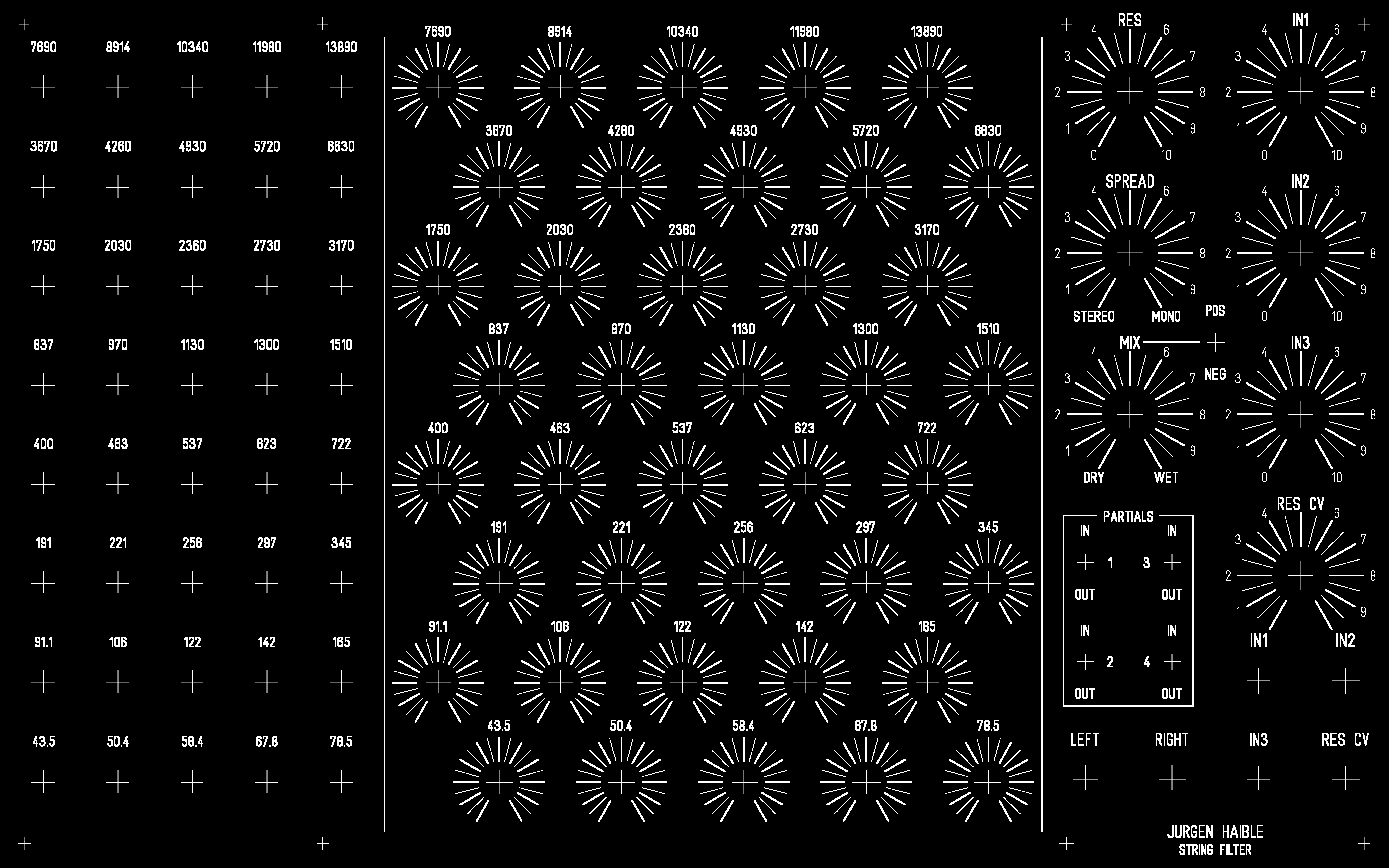
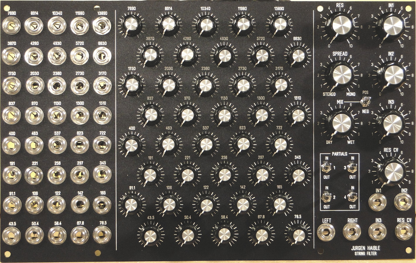
Panel Layout
I bought a sheet of 1/8" plastic (clear lexan) at a hardware store and cut that into a 5U by 8U piece. I made an inverted printout of the panel in Front Panel Designer (black text on white background) and used that as a guide for drilling the holes in the plastic. I then printed out a screenshot of the FPD file using a laser printer and pasted it onto one of the plastic panels. In order to get smooth diagonal lines in the printout, I had to enlarge the panel (in Front Panel Designer) by 400% and then make multiple screenshots and stitch them together in a graphics program. Finally, I used an X-Acto knife to carefully remove the paper that covered the holes. The end result is not as sturdy as a metal panel, and doesn't provide any shielding, but it looks quite good and most people can't tell it's any different from the metal panels in my synth. I used a mix of large and small knobs in this design to make it all fit into 8U wide. I used large knobs for the main control section. The 40 filters use small knobs on a staggered grid to make them easy to access without taking up too much space. The jack field is compressed a bit (compared to most MOTM format panels) but still works well with the wider Neutrik phone plugs. |
||||||||||||||
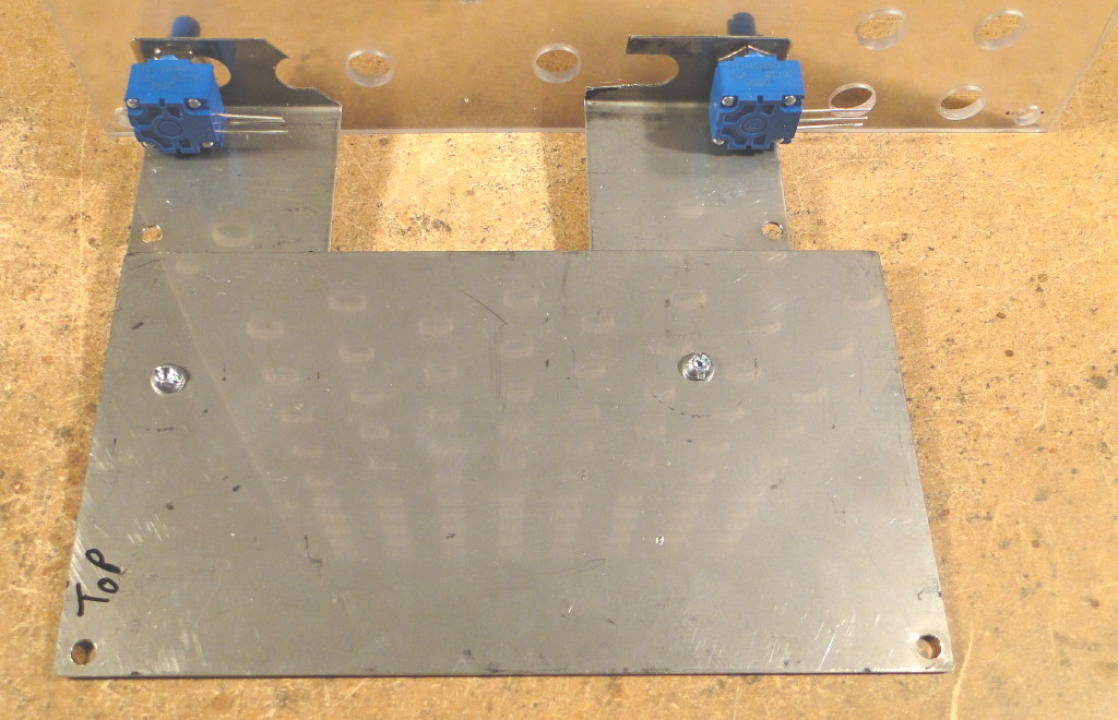
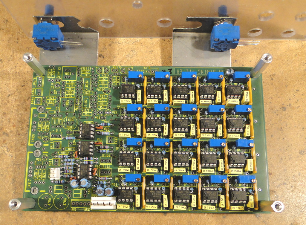
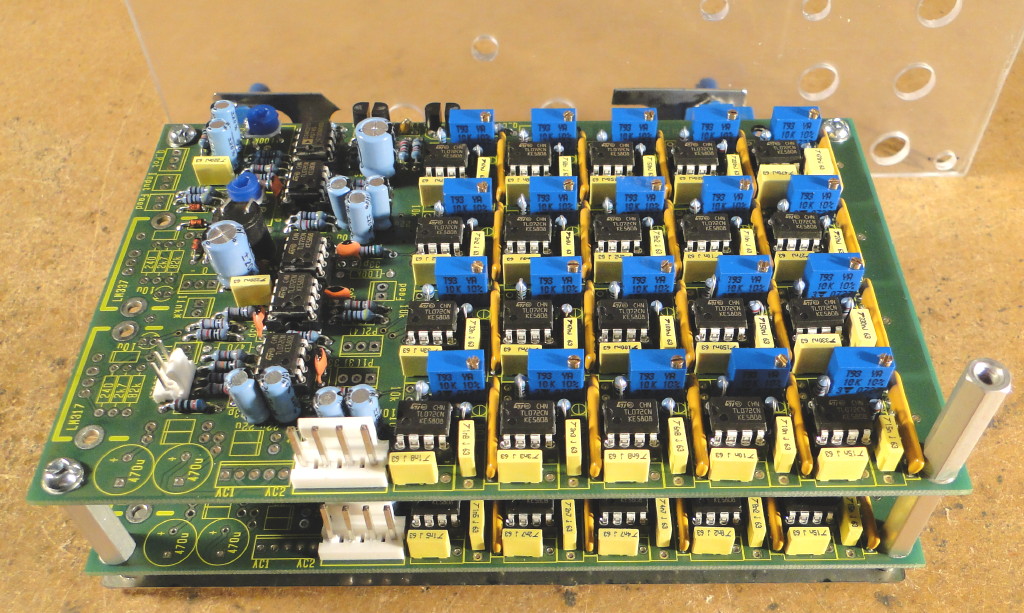
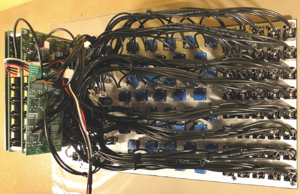
Construction Photos
|
||||||||||||||
Sample SoundsPink Noise ExperimentsThe following three selections all use pink noise as the input to the string filter.
Vocal Formant ExperimentsThe following three selections all use a sawtooth wave with a bit of frequency modulation as input to the string filter. On its own it sounds like this. Five of the level controls are set to produce a single vocal formant. The other 35 controls are set to zero. The individual outputs are used to create two additional vocal formants (using external mixers to set the levels). Five frequencies are used for each of these two formants as well. Some switching logic is used to sequence through the three formants.
|